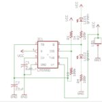
Basic LED Blinker Circuit
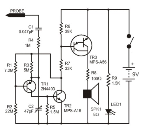
Capacitance Beeper
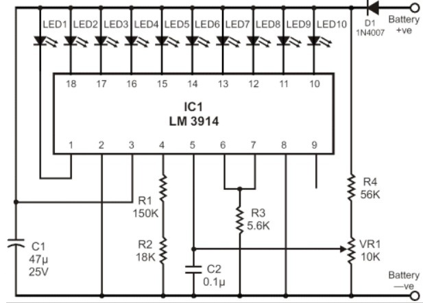
Battery Monitor
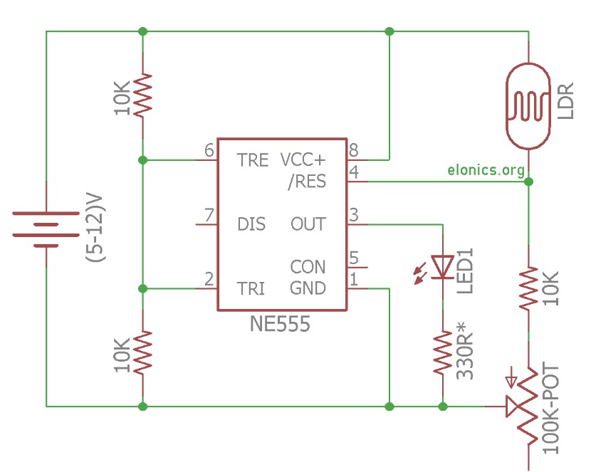
Adjustable Light Sensor Schematic
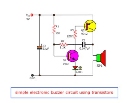
Simple Buzzer Alarm
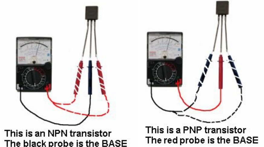
Transistor Tester