ESP32 E-Paper Weather Dashboard: Design Overview
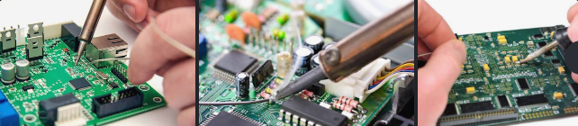
This article is a design outline for an ESP32 desktop weather display. It describes the main hardware blocks and the checks needed before making a PCB. The photographs are illustrations; they are not proof that the exact circuit or firmware below has been built and tested.
What the design needs to do
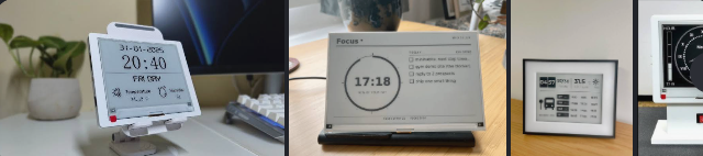
An ESP32 can connect to Wi-Fi and retrieve current weather data from a service such as OpenWeather. A BME280 can provide separate indoor temperature, humidity and pressure readings. An e-paper module can show the information without a constantly lit backlight. These are three separate functions: the sensor does not supply the internet forecast, and the display will not update until suitable firmware drives it.
Parts to select
- An ESP32 development board for the prototype, or an ESP32-WROOM module with the supporting power, reset and programming circuitry specified by its manufacturer for a custom board.
- A 4.2-inch e-paper module with a known controller and an ESP32-compatible interface. “4.2-inch” alone is not enough to select a display driver.
- A BME280 breakout board for indoor readings. Confirm its supply voltage and interface pins from the exact board documentation.
- A suitable USB power arrangement and a 3.3 V regulator sized for the peak current of the chosen ESP32 and display. Select protection and USB components from their datasheets.
Architecture and PCB checks
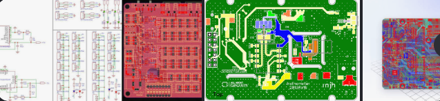
The e-paper module normally communicates over SPI, while the BME280 commonly uses I²C. Make a pin table for the actual display module before assigning ESP32 pins. Check the display controller, logic voltage, busy/reset lines and library support. Keep the ESP32 antenna clearance required by its manufacturer and place local decoupling parts as the module and regulator datasheets specify. Run electrical-rule and design-rule checks before ordering a board. Trace widths and regulator ratings must be calculated for the real current and copper stack-up rather than copied from a generic example.
A sensible prototype sequence
- Identify the exact e-paper controller and use the matching example in the display library to confirm that the screen can draw a simple message.
- Read the BME280 separately and label its readings as indoor measurements.
- Test Wi-Fi and the weather API separately. OpenWeather’s current-weather endpoint requires a location and an API key; request metric units if you want Celsius. Check HTTP status and JSON parse errors rather than assuming every response contains weather data.
- Combine the tested pieces. Update the screen only after new data is valid, and make the refresh interval appropriate for the chosen panel and API plan.
- Only then translate the prototype into a schematic, PCB and enclosure matched to the measured power and physical dimensions.
Firmware scope
The earlier code fragment in this article was incomplete: it had malformed includes, a placeholder URL and no e-paper drawing routine. It has been removed so it is not mistaken for a working sketch. A finished program needs a display driver for the exact panel, Wi-Fi reconnect handling, a weather request, JSON error handling, text layout and an update schedule. Start with the GxEPD2 examples for your panel and the OpenWeather current-weather API documentation for the response fields. The ArduinoJson HTTP example shows how to check a parsed response. These are reference starting points, not a validated combined sketch for this particular hardware.
Before calling it a finished build
Record the exact part numbers, pin map, schematic, measured current, board files, firmware version and photographs of the assembled unit. Test a failed Wi-Fi connection and a failed API request as well as the normal display update. That evidence turns this concept into a repeatable build guide.