

PCB Electronics
Basic DC Circuits
Understanding Schematic Diagrams and Symbols
You’ve already encountered some basic electrical circuit diagrams. Many of these use the same symbols that professional technicians and engineers rely on. In this chapter, you’ll deepen your understanding of these diagrams and explore the relationships between current, voltage, resistance, and power in both direct-current (DC) and low-frequency alternating-current (AC) circuits.
Schematic Symbols
Rather than simply memorizing schematic symbols, this course emphasizes learning them through practical use—reading and applying them in real-world scenarios. However, it’s helpful to familiarize yourself with these symbols beforehand, here’s a quick overview of some common ones.
Wires & Conductors: A straight, solid line represents an electrical conductor. While dotted lines are sometimes used, they typically indicate circuit partitions or interactions between components. Conductors are usually drawn in neat horizontal or vertical lines to maintain clarity.
Wire Junctions & Connections: When two conductors cross, they are only electrically connected if a black dot is placed at the intersection. This dot must be clearly visible to indicate a proper connection.
Resistors & Potentiometers: A resistor is represented by a zigzag line, while a variable resistor (or potentiometer) is shown as a zigzag line with an arrow passing through it.
By recognizing and understanding these symbols, you’ll be better equipped to interpret and design circuits with confidence.
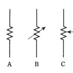
A: A fixed resistor.
B: Two-terminal variable resistor.
C: A three-terminal potentiometer.
A battery, consisting of multiple cells connected in series, is represented by a set of four alternating long and short parallel lines (long-short-long-short). While some diagrams may use six or even eight lines, four is typically sufficient. Below are the standard symbols for a single cell and a battery.
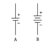
A: A single cell.
B: A battery.
Meters are represented by circles in schematic diagrams. Some may include an arrow inside the circle, while others display the meter type—such as mA (milliammeter) or V (voltmeter)—either inside or beside the circle. Both notations are acceptable, but consistency throughout the schematic is key.
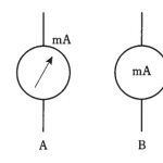
Meter symbols.
A: Designator outside.
B: Designator inside.
Either symbol is ok.
Other commonly used symbols include those for a lamp, capacitor, air-core coil, iron-core coil, chassis ground, earth ground, alternating-current source, terminal set, and the “black box”—a rectangle with a label inside indicating its function. These symbols are illustrated below.
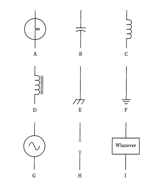
Nine common schematic symbols. A: Incandescent lamp.
B: Capacitor. C: Air-core coil. D: Iron-core coil. E: Chassis
ground. F: Earth ground. G: Source of alternating current (ac).
H: Pair of terminals. I: Specialized component or device. Click the picture to enlarge.
Schematic Diagrams
A schematic diagram is a simplified representation of an electrical circuit, using standardized symbols to illustrate components and connections. It provides a clear and concise way to understand and design circuits, making it an essential tool for engineers, technicians, and hobbyists.
Wiring Diagrams
The key difference between a schematic diagram and a wiring diagram lies in the level of detail. A schematic diagram illustrates how components are interconnected but doesn’t always specify their exact values or ratings. For example, you might see a two-transistor audio amplifier diagram with resistors, capacitors, and transistors, but without any information on component values. While this provides an overview of the circuit’s design, it isn’t enough to physically assemble and operate the circuit.
If you were to build the circuit, you’d need additional details—such as resistor values, capacitor types, and suitable transistors. Would the coils need to be custom-wound, or could they be store-bought? Should test points or special terminals be included for troubleshooting? How much power should the potentiometers handle? A wiring diagram includes all these specifics, making it a more detailed, practical guide for assembling and servicing electronic devices. You’ve likely seen such diagrams in the back of manuals for hi-fi amplifiers, FM tuners, or televisions, where they are crucial for repairs and maintenance.
Voltage, Current, and Resistance in a Circuit
Most DC circuits can be simplified into three essential components: a voltage source, conductors, and resistance. This fundamental relationship is illustrated in the schematic diagram below. In circuit notation, the voltage or electromotive force (EMF) is represented by E, the current flowing through the conductor is I, and the resistance is R. These components are measured in volts (V), amperes (A), and ohms (Ω), respectively—the standard units in electrical systems.
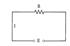
Simple DC circuit.
The voltage is E,
and the current is I,
and the resistance is R.
As you are well aware, these three quantities are related. If one of them changes, the other one or both will follow suit. The current will increase as the resistance decreases. The current will drop if the EMF source is made smaller. The voltage across the resistor will rise in response to an increase in the circuit’s current. These three quantities have a straightforward arithmetic relationship.

