
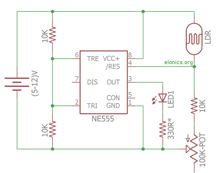
Adjustable Light Sensor Schematic
Project details
Light Sensor Circuit Using LDR and 555 Timer IC with Adjustable sensitivity
In this tutorial we’ll learn how to make a light sensor circuit using LDR (Light Dependent Resistor), 555 timer IC and a few other electronics components. This circuit detects light incident on the LDR and turns on LED whenever the intensity of light is greater than a certain level.
The LED can be replaced by any electronic device like buzzers, relays. DC motors etc. We will learn more about that later in this tutorial. We will also learn how this circuit works and other cool stuff that can be done with this circuit. So let’s get started.
Components Required
- 555 Timer IC
- Light Dependant Resistor (LDR)
- Resistors: 2 x 10K, 330R
- 100K Potentiometer
- Light Emitting Diode (LED)
- Breadboard
- Few Breadboard Connectors
- (5-12)V Power Supply
Okay, let’s break down how this circuit works in a more clear and organized way!
Understanding the Basics
- Light-Dependent Resistor (LDR):
- An LDR is a special resistor that changes its resistance based on how much light hits it.
- When it’s bright, the LDR’s resistance goes down.
- When it’s dark, the LDR’s resistance goes up. Think of it like a dimmer switch for electricity, controlled by light.
- 555 Timer IC:
- This is a versatile chip that can do lots of cool things, like timing events and creating signals.
- In this circuit, we’re using it as a switch that turns on and off based on the light level.
- It has a reset pin (pin 4) that when the voltage is greater than 0.8 volts, it will activate.
- Pins 2 and 6 need to be between 1/3 and 2/3 of the voltage supplied to the chip, to allow the output to be on.
How the Circuit Works
- Voltage Divider:
- We’ve set up a voltage divider using the LDR, a regular resistor, and a potentiometer (a type of adjustable resistor). This lets us create a voltage that changes with the light level.
- This voltage is connected to the reset pin (Pin 4) of the 555 timer IC.
- Light and Voltage:
- When it’s dark, the LDR’s resistance is high, so the voltage at Pin 4 drops below 0.8 volts, and the 555 timer turns off.
- When it’s bright, the LDR’s resistance is low, so the voltage at Pin 4 goes above 0.8 volts, and the 555 timer turns on.
- Output Control:
- Two 10k resistors are used to divide the supply voltage in half, and that voltage is connected to pins 2 and 6. This allows the 555 timer to turn the output on when it is activated by the reset pin.
- LED:
- In our example, we used the 555 timer to turn an LED on and off.
Making it More Powerful
- Relays:
- Instead of just an LED, you can use a relay. A relay is like an electrically controlled switch that can handle higher voltages and currents. This lets you control things like lamps, motors, or other appliances.
- Light Alarm:
- You can also configure the 555 timer to create a buzzing sound and connect a speaker. This would create a light-activated alarm.
Where You Might See This
- Automatic Streetlights:
- These circuits can be used to automatically turn streetlights on at night and off during the day.
- Wardrobe Lights:
- They can be used to turn on lights inside closets or lockers when you open them.
- Security Systems:
- Light-sensitive burglar alarms can use these circuits to detect changes in light levels.