Understanding Logic Gates: The Building Blocks of Digital Circuits
In the world of electronics, logic gates serve as the foundation for digital circuits. Whether you’re designing a simple LED flasher or a complex microprocessor, logic gates play a crucial role in processing and controlling signals. In this blog, we’ll explore what logic gates are, their types, and how they work.
What Are Logic Gates?
Logic gates are electronic circuits that perform logical operations based on binary inputs (0s and 1s). These gates operate using Boolean algebra and are fundamental to digital electronics, including computers, microcontrollers, and embedded systems. Each logic gate follows a specific rule that determines its output based on the given inputs.
Types of Logic Gates
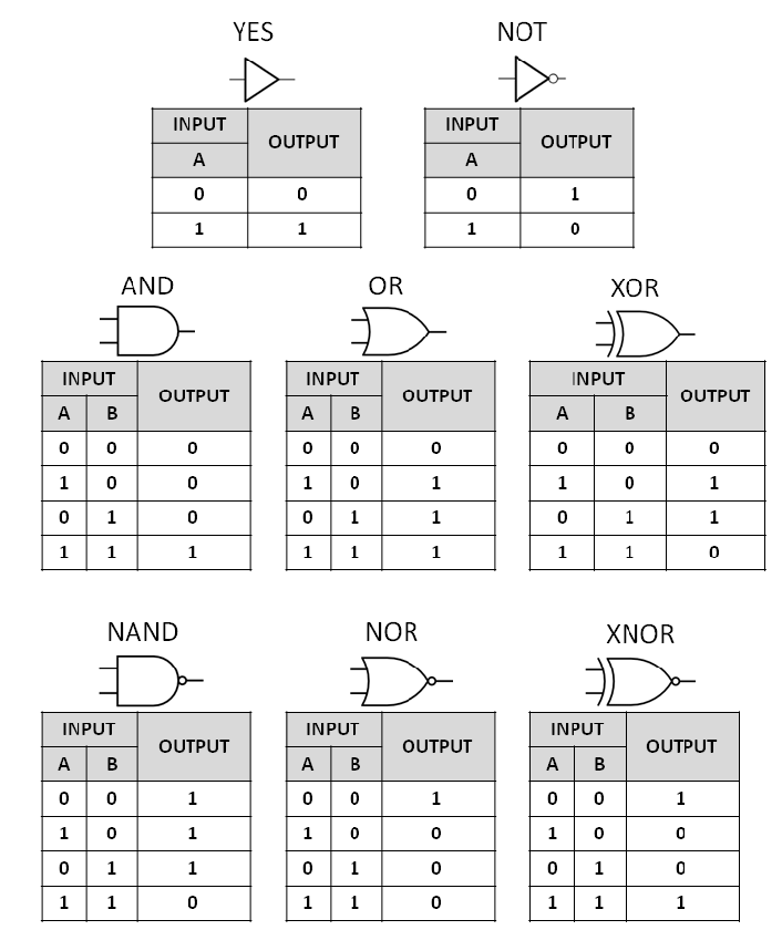
1. AND Gate
The AND gate produces an output of 1 (HIGH) only if both of its inputs are 1. Otherwise, the output is 0.
| Input A | Input B | Output |
|---|---|---|
| 0 | 0 | 0 |
| 0 | 1 | 0 |
| 1 | 0 | 0 |
| 1 | 1 | 1 |
2. OR Gate
The OR gate produces an output of 1 if at least one of the inputs is 1. The output is 0 only when both inputs are 0.
| Input A | Input B | Output |
|---|---|---|
| 0 | 0 | 0 |
| 0 | 1 | 1 |
| 1 | 0 | 1 |
| 1 | 1 | 1 |
3. NOT Gate (Inverter)
The NOT gate, also known as an inverter, flips the input. If the input is 1, the output is 0, and vice versa.
| Input | Output |
|---|---|
| 0 | 1 |
| 1 | 0 |
4. NAND Gate
The NAND gate is the opposite of the AND gate. It gives an output of 0 only when both inputs are 1; otherwise, the output is 1.
| Input A | Input B | Output |
|---|---|---|
| 0 | 0 | 1 |
| 0 | 1 | 1 |
| 1 | 0 | 1 |
| 1 | 1 | 0 |
5. NOR Gate
The NOR gate is the opposite of the OR gate. It gives an output of 1 only when both inputs are 0; otherwise, the output is 0.
| Input A | Input B | Output |
|---|---|---|
| 0 | 0 | 1 |
| 0 | 1 | 0 |
| 1 | 0 | 0 |
| 1 | 1 | 0 |
6. XOR Gate (Exclusive OR)
The XOR gate produces an output of 1 if only one of the inputs is 1. If both inputs are the same, the output is 0.
| Input A | Input B | Output |
|---|---|---|
| 0 | 0 | 0 |
| 0 | 1 | 1 |
| 1 | 0 | 1 |
| 1 | 1 | 0 |
7. XNOR Gate (Exclusive NOR)
The XNOR gate is the inverse of XOR. It produces an output of 1 if both inputs are the same (either 0,0 or 1,1) and 0 otherwise.
| Input A | Input B | Output |
|---|---|---|
| 0 | 0 | 1 |
| 0 | 1 | 0 |
| 1 | 0 | 0 |
| 1 | 1 | 1 |
Applications of Logic Gates
Logic gates are used in almost every digital device, including:
- Computers and Microprocessors – The CPU processes binary data using millions of logic gates.
- Memory Devices – RAM, ROM, and storage devices rely on logic circuits.
- Automated Systems – Logic gates control industrial automation, sensors, and robotics.
- Digital Clocks and Timers – Used in digital watches and scheduling circuits.
- Home Electronics – From remote controls to smart appliances, logic gates are everywhere.
Conclusion
Logic gates are essential in digital electronics, forming the backbone of modern computing and automation. Understanding how they work can help you design and troubleshoot digital circuits effectively. Whether you’re working on a simple Arduino project or designing a custom PCB, mastering logic gates is a fundamental skill in electronics.